
Silicon Carbide (SiC) Heating Elements
Silicon Carbide (SiC) Heating Elements from Silcarb
Silcarb is the market leader of Silicon Carbide Heating Elements. Our SiC Heating Elements are known under the tradename of “Alpha Rod, Alpha Ultra Rod, Alpha Ultra Spiral”
The Alpha Rod component could be a resistance kind carbide component. The factors are thick-walled tubes. they need a heat section mentioned as a heat sector and 2 terminal sections known as cold ends. The bloodless ends are fertilized with the atomic number 14 metal to lower their resistance and permitting them to operate at a decrease temperature. The extremities of the weather ar metalized with atomic number 13 to produce a coffee resistance contact floor to that the electrical connections are created with adorned atomic number 13 straps. components are delineated by victimization giving the same old length, the heating space length, the diameter, and resistance..
Silcarb is the No1 manufacturer of following types of SiC Heating Elements
- Three Piece Straight Alpha SIC Rods – Silicon Carbide Heaters
- Alpha Ultra Rod Single Piece Element
- Reaction Bonded Single Spiraled Heating Elements
- Reaction Bonded Double Spiraled Heating Elements
- U-Shaped Alpha SIC Rods
- Dumbell Shaped Silicon Carbide Heating Elements
High-Performance SIC Heating Component from Silcarb
The Alpha Rod components can provide you with superior performance thanks to their high density of 2.4gms/cc or higher. this offers the part terribly slow ageing characteristics and extra strength.
Special Surface Coatings
Various types of coatings are provided onto the alpha rods. These range from glass coatings to CVD coatings for particular applications. We have a coating for assaying furnaces (i.e lead attack) and coatings for use in high vacuum applications and coating for use in reducing atmospheres.
Do get in touch with us and let us know about your applications and atmospheres in which you wish to use the heaters and we will suggest the right surface coating for the application.
Very High Operating Temperatures
The Alpha Rod components are often operated at chamber management temperatures up to 1550°C in an associate degree air atmosphere or inert atmospheres of atomic number 18 or inert gas. In reducing the atmosphere the most counseled operational temperature is 1350°C.
Characteristics of Silicon Carbide Heaters – Alpha Rod Elements
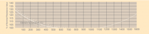
The Alpha Rod element is a linear type resistance heater that converts electrical energy to heat energy (Joule’s Law W=I2R). W=power in watts, I=current in amperes, R=resistance in ohms. The heating parts are usually said as self-bonded, for the lattice structure or bonds that hold the weather along that are fashioned by recrystallizing the carbide at terribly high temperatures. the weather ar factory-made of an inexperienced carbide that is classed as Associate in Nursing excess lepton sort semiconductor. The resistance of a carbide part is tough to live at temperature because of minor impurities, self-heating, and phone resistance. Also, carbide encompasses a negative resistance temperature characteristic from temperature to close to 800°C. It turns positive at now and remains therefore throughout its traditional operational temperature vary.A typical resistance-temperature graphical record of a carbide component. Nominal element resistance is measured at a standard calibrating temperature of 1050°C. Resistance Values of elements are shown on the physical and electrical characteristics pages
Service Life
The Alpha Rod heating elements increase gradually in resistance with use. This characteristic of increasing resistance is called ageing. Ageing is a function of the following:-
- Operating temperature.
- Electrical Loading – Usually Expressed in watts per square centimeter of element radiating surface.
- Atmosphere.
- Type of operation
- Operating and Maintenance Techniques.
Mounting of Silicon Carbide Heating Elements
There aren’t any restrictions on the mounting positions of Alpha Rod components, though the horizontal and vertical positions ar the additional common. Extreme caution should be used when mounting to ensure that the elements are not placed in tension. There ought to be adequate freedom to permit the chamber and parts to expand and contract severally. once mounting parts vertically they need to be supported on the lower finish by electrically insulated supports. Alpha Rod parts ought to have their heating sections centered within the chamber so no portion of the heating section extends into the chamber wall. A round shape or truncated round shape recess ½ in. deep is found on every interior wall wherever the component passes through. This allows the recent zone to radiate properly and helps maintain a homogenous temperature within the oven.
Ordering With Silcarb
Alpha Rod parts square measure mere as follows:-
Diameter / Hot zone length / Overall length / Nominal resistance.
Ordering Type SE Elements are specified as follows:
Diameter / Hot zone length / Overall lengths / Nominal resistance. Spiroheat Type Double End elements can also be provided with offset Hot zones i.e., unequal cold finish lengths and additionally split hot zones for central support in exceptionally long hot zones. Please specify your precise needs. ideally with drawings whereas ordering. nearer tolerances on-resistance will be provided at Special rates.
Electrical Characteristics of ‘spiro Heat / Alpha Rod Elements
The resistance of spiroheat / Alpha rod Element varies with temperature as detailed in the figure below. From relatively high value at room temperature it falls to a minimum at about 800oC and then gradually rise upto its maximum operating temperature.
The voltage across the component and also the current passing through it ought to be measured at concerning 800oC. The voltage across the element and the current passing through it should be measured at about 800oC to determine the resistance (V=IR)

Operating Temperatures
Spiroheat / Alpha Rod elements may be operated in air at furance temperature of upto 1550o C. Elements may also be used in neutral or reducing atmosphere but a lower temperature limit may be required. Maximum recommended operating temperatures for Spiroheat/ Alpha Rod Elements in various process atmospheres.
(Note that element temperatures are quoted and that these may be Considerably higher than the furnace temperature)
Element Loading
The operating temperature of the elements is dependent on both the furnace temperature and the specific element loading, normally expressed in watts per square centimeter of the Hot zone area
Resistance / Temperature Characteristics
Effect of Atmospheres
Spiroheat / Alpha Rod elements are normally operated in air or other oxidizing atmospheres, as other gases may react with the element material or the protective glaze, thereby causing a reduction in element life. It is recommended that the manufacturer be consulted if the use of Spiroheat Element in a reducing atmosphere is being considered.
Water vapour has a serious effect on ‘Spiroheat / Alpha Rod Element’, by increasing, the oxidization of the material and hence the ageing rate. Furnace should be thoroughly dried before the elements are installed but if it is essential to use the elements for drying, then the furnace should be well ventilated and no build up of steam should be allowed to occur.
Other process vapours may also adversely affect element life, either by chemically attacking the silicon carbide andthe protective glaze or by condensing in the element support holes causing restriction and subsequent breakage. Most alkali vapours will have a detrimental effect, halogen gases, metal halides (e.g. Fluxes in aluminum furnaces) and also most of the metallic oxides.
To minimize any attack an efficient extraction system should be incorporate to reduce the volatile concentration in the chamber to an acceptable level. This will also encourage an inflow of air over the element cold ends and minimize any condensation at these points.
Installation Methods
The elements must be accurately positioned in the furnace to ensure that the hot zone does not enter the element support holes. It is important to ensure that elements are free to move in all directions and mounting holes must be aligned and sufficiently large to prevent restriction, for expansion during hot condition.
Type DE / Alpha Rod Elements
Special lead-in sleeves are available for each size of element. They should be fitted from the outside of the furnace in holes bored to a diameter which will ensure a loose fit. Sleeves should never be cemented into position. If sleeves are not used then the element support holes should be about 3-6mm large than the element diameter for sizes up to 18mm about 8-10mm for larger sizes. For exceptionally thick furnace lining and where there is a possibility of volatiles condensing on the cold ends, a fairly large hole diameter should be used and the elements centralized by supporting them on a small ceramic fiber pad under cold end
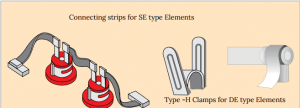
Type SE Elements

Special lead-in sleeves are recommended for use with SE elements to provide the correct alignment and support required. These sleeves should be of a loose fit and not cemented into positions. Type SE Elements can be mounted horizontally or vertically, projecting up or hanging down. The terminal assembly should be outside the furnace
structure to keep it as cool as possible. No Portion of the spiral heating section should extend into the refractory wall. The element should be mounted in a high Die-electric lead-in sleeve to prevent possible shorting of the terminal ends, because full element voltage exists along the entire length of the Terminal.
Installation and Maintenance
- The correct size of elements should be chosen at the design stage of the furnace. This is to ensure that the wattage loading does not exceed that shown in the Element Loading graph.
- The element support holes must be of the right size, i.e. 3 to 6 mm larger than the element diameter upto 18 mm and 8-10 mm for larger sizes and should be installed along with ceramic lead-in sleeves for both type DE & SE Elements.
- The aluminium braid connections should be flexible and long enough to avoid any stress on the elements.
- Connecting spring steel clips tend to loose their tension over a period of use. Therefore, new clips should be used when ever an element is replaced.
- When elements are connected in series it must be ensured that they are well matched in resistance. Generally not more than 2 elements should be connected in series.
- If an element breaks prematurely due to mishandling it may be replaced with a new one. However, if the furnace has been run for a long period, it is preferable to replace the full set of elements owing to the incompatibility of resistance due to ageing. Partially aged elements may be stored for later use with others of the same resistance.
- When starting with new elements always select the minimum voltage tapping available.
- When an element is used continuously as in the case of a tunnel Kiln, special glaze treatment is required. Please specify use while ordering. It is recommended that a chart of the elements resistances be maintained and the resistance values of the elements operating be entered every 15days. This helps to monitor the life of the elements.
- As these elements are fragile, handle with care, particularly whilst fitting the braids and clamps.
- Block off the annular space between the element and the surrounding refractory with ceramic fibre of glass wool to prevent heat loss at the cold ends.
Accessories
Silcarb manufactures a range of element connections To suit its Spiroheat / Alpha Rod Elements
- Connecting Braids – Aluminum Braid is recommended for making all element connections because of its high conductivity, flexibility and resistance to oxidation at high temperatures.
- Terminal Clips: Alpha Rod / Spiroheat type DE & SE elements are supplied with complete terminal Accessories including lengths of aluminium braid for connection to the power supply. In a majority of applications where the terminal ends are well ventilated and unlikely to exceed temperatures of about 250oC, connections are made by wrapping the aluminium braid around the terminal end and securing with Type H spring clips, and are fitted manually. Silcarb recommends that terminal clips should be changed with the element as the clips tend to lose their tension overa period of time.
- Special lead – in sleeves can also be provided along with the elements. The inner and outer diameters of the lead – in sleeve are fixed depending upon the diameter of the element. How ever the length of the lead-in sleeve, depend upon the insulation thickness of the furnace. While ordering please mention length of the lead- in sleeve necessary for your requirements
Power Input
A variable voltage source is necessary to provide power input to the heating elements to offset the drop in rating due to the aging of the elements with use. A transformer (tapping or continuously variable) or a thyristor drive would serve the purpose. However, it is recommended that a 100% voltage reserve be provided to ensure the maximum life from the heating elements. In case of stepped output tapping transformer, it should be ensured that adequate taps are provided. It is recommended that a minimum of 8 Stepped outputs or taps be provided to ensure that the elements are not drastically overloaded While changing from one tap to the next higher one.
Element Spacing
Alpha Rod / Sprioheat Element should be spaced at a minimum of 1 diameters between element centres and the refractory lining. A clearance of at least 2.5 diameters should be allowed between the element centres and the wall, but it may be necessary to increase this if uniformity of heating is required, especially if the distance between adjacent elements is large
A = ( 1.5 x D) = Minimum spacing between element centre and adjacent refractory
B = ( 2.5 x D) = Minimum spacing between adjacent element centres
C = ( 1.5 x D) = Minimum spacing between element centres and hearth plates or work
D = Element Diameter

Note: if under heating is to be used, then the hearth plates should have a good thermal conductivity. Suggested material being Silicon Carbide
Silcarb today is India’s leading manufacturer of Silicon Carbide Elements. Silcarb has been manufacturing heaters now in Bangalore, India for the last three decades. Silcarb is known for its high quality and fast response time to customer needs. Due to high volumes of production, Silcarb is also able to price its products competitively. Silcarb is constantly innovating to reduce energy consumption for both its customers & its own in-house production facilities. Environmental protection has been one of Silcarb’s highest priority.
For further information, Please Click on PDF Brochure Download link:> Silcarb SiC Heating Elements Brochure
Primary Sidebar
Quick Contact
Fields marked with an * are requiredFirst Name *Last Name *Email *Phone *Details *
Footer
About Silcarb Recrystallized
From the year 1982 onwards manufacturing SiC Heaters and holding more than 90% of the current market in India and exporting all over the world. Silcarb now boasts of a range of high density MoSi2 heater range, a wide customer centric Kiln Furniture production center, and a brand new facility for the manufacture of fine Technical Ceramics including Nitrides, Carbides and Titnates. Silcarb has the following manufacturing divisions:-
- 1. Silicon Carbide (SiC) Heating Elements Division
- 2. Molybdenum Di-Silicide (MoSi2) Heater Division
- 3. Furnace Manufacturing Division
- 4. Kiln Furniture Division
- 5. Technical Ceramics Division
Get in Touch with Team Silcarb
Our Products
- Silicon Carbide (SiC) Heating Elements
- Molybdenum Disilicide (MoSi2) Heating Elements
- Industrial Furnaces
- Kiln Furniture
- Technical Ceramics
Our Quality Standards
Silcarb Recrystallized Private Limited.
No-38, 17th Cross, Malleswaram,
Bangalore-560 055, India.
+91-80-23347004 (10 lines)
